When a node is "tethered", it is linked in one or more directions to other nodes (the "Primary" node). Both nodes (Tethered and Primary) actually share the same degree of freedom for the direction of tethering. The tethering can be for any or all of the three global degrees of freedom. A node can be tethered to more than one node (in different directions). Any number of nodes may be tethered to the same primary node, but the primary node itself may not be tethered to another node.
Note:
An example of the use of nodal tethering is in X bracing, where the bracing members overlay and are pinned to each other. Modeling this connection makes the analysis far more complex than simply modeling the braces as separate pieces, and is generally not recommended. However, if it is desired to specifically account for interaction between the braces then this pinning will force the brace midpoints to deflect together for translations, but still leave them free to rotate independently.
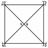
In this diagram the braces are NOT modeled as physical members. Brace 1 to 3 is modeled with non physical members from nodes 1 to 5 and 5 to 3. Brace 2 to 4 is modeled with non physical members from nodes 2 to 6 and 6 to 4. Nodes 5 and 6 are at the same location where the braces overlap and are pinned together.
We would tether node 6 to node 5 for the translation directions. To define a tethered node, use the Boundary Conditions spreadsheet. Enter the label of the node to be tethered as the "Node No.", and for the directions in which it is tethered, enter TETHER nnn, where nnn is the label of the primary node.
For this X brace example, we would enter the following on the Boundary Conditions spreadsheet:
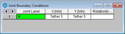
Here we have "TETHER 5" entered for the X, and Y translations. The rotation field is left blank because node 6 is free to rotate independently. We don't have to enter anything for node 5.